
Přemek Koch
Okružní 1872
73701 Český Těšín
CZECH REPUBLIC

Putting up the mast - part 1. | 7. 08. 2014 09:27 |
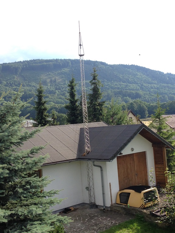
As probably every Ham, I also dreamt about a nice mast with an antenna system. For a long time I was considering what mast to get and where to put it to get the best results. XYL had no objections. When I finally decided to install a 10 m long pneumatic mast in the attic of the garage (so that the…
More ▼
Putting up the mast - part 2. | 7. 08. 2014 11:41 |
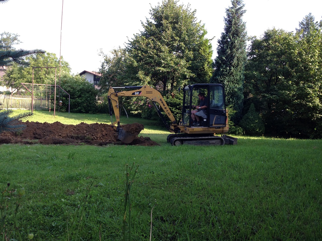
Once I successfully finished putting up the mast I had to think about the cable route between the mast and the hamshack. I looked up some information on the internet that described a set up similar to mine. I was especially concerned with how to ground the whole thing properly so as to avoid ground…
More ▼
Putting up the mast - part 3. | 12. 08. 2014 08:19 |
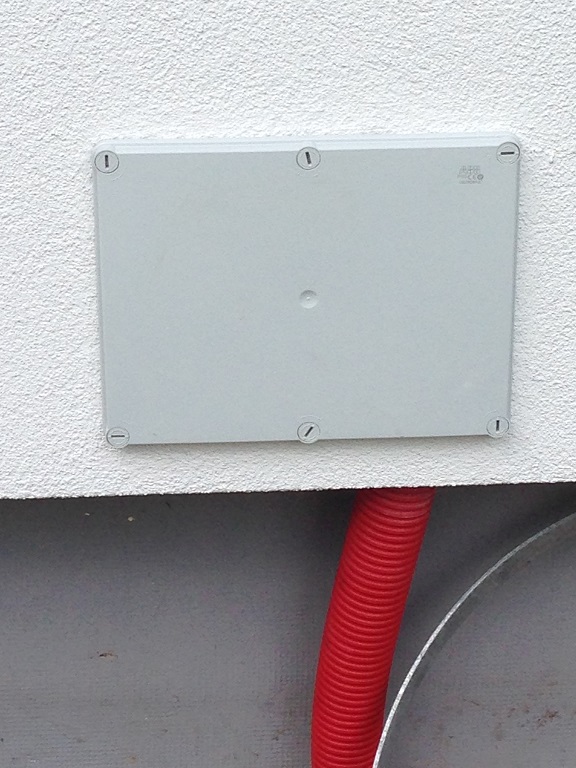
The weather throughout the week was good so I prepared everything to put down the wiring. I had to attach a grounding box to the outside wall of the hamshack. This will contain grounding for all the cables before they enter the hamshack. I will also put the lightning arrester for the coaxial cable…
More ▼
TRX210 Sněžka for long evenings | 24. 01. 2023 19:31 |
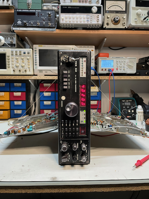
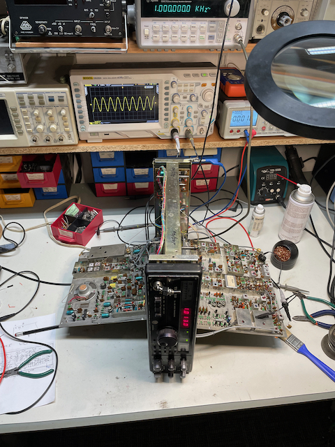
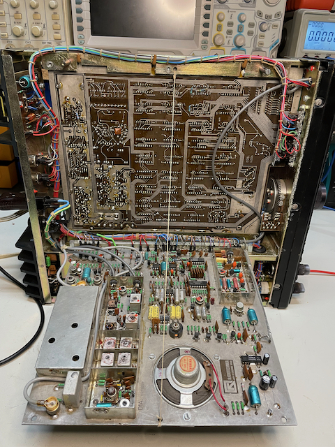
During the repair of the TRX210 Sněžka transceiver, which was entrusted to me by Luďek OK2KZ, I worked up a sweat diagnosing and repairing interesting fault. Since I could not find any mention of a similar problem on the Internet, I decided to write my anabasis on my blog. I've only noticed sighs over the unstable VCO, which could be correlated with my glitch and its cause. To the knowledgeable reader, some of my diagnostic procedures and steps may seem a bit non-standard - I would like to state here that I am self-taught and mostly stumble upon lack of experience. Here again I have gained some valuable ones, for which I am glad and which is the reason why I am engaged in this field. But let's get to the glitch itself.
While reviving the transceiver, I noticed on the SSB reception that the pass band of the second intermediate frequency seems to open up completely randomly. Thanks to the included crystal filter, this band should be about 2.5kHz wide. However, if I tuned above the received signal just slightly beyond the edge of the filter and left the trx alone, the signal penetrated the demodulator at irregular intervals for an irregular period of time. Likewise, if I was tuned to the passband, the received demodulated tone changed in frequency. Such symptoms in themselves indicate a drifting VCO, but here one more symptom confused me - if there was a malfunction, tuning the trx in the 10kHz range had no effect, the tone did not change, only the displayed frequency changed as it should. After exceeding 10kHz (or after changing values of tens of kHz on the scale) the error seemed to mysteriously disappear and until the next occurrence the trx was receiving completely normally. What made it worse was that the fault often appeared as a cold connection - sometimes it disappeared after tapping the table or the trx, sometimes I could bang all I wanted and nothing changed. Just uncovering all these manifestations and connections took me a lot of time even during the repair itself, which gradually refined my search. That's why my first steps may look a bit illogical...
Checking the connections in the second IF part, I didn't find anything wrong. Looking at the schematic, I suspected a bypass path for FM modulation that bypasses the SSB crystal filter. I measured the specific switching diodes and the voltage across them, which was more difficult than it seems due to the random and time-invariant occurrence of the fault. However, I didn't find a problem here either.
In the next step, I started suspecting and checking the AVC circuits. Although an error in these circuits probably could not cause such strange behavior, I fell a little bit into believing in ghosts, modulation of transistors by poorly filtered control voltage, HF penetration everywhere and similar tricks that came to my mind. After many measurements and attempts, I finally disconnected the AVC control voltage and simulated it from an external source, and I had to state that there is no error here either.
Subsequently, I suspected mechanical damage to the filter itself. I would like some experience here, whether such damage is even possible, when the width of the filter can change in this way due to a mechanical defect. I pulled the filter out of the board and roughly measured it on the generator and spectrometer. Alas, it worked flawlessly, this too was a dead end.
I moved to the pre-filter to the mixer section and began to suspect that one of my frequencies fault. Since the "main" VCO is basically digitally controlled and controlled by a PLL loop, and since the PLL failure detection led didn't indicate anything suspicious, I focused on the 12.4MHz oscillator. By checking and measuring, I had to state that it is off by a few tens of Hz, but stable.
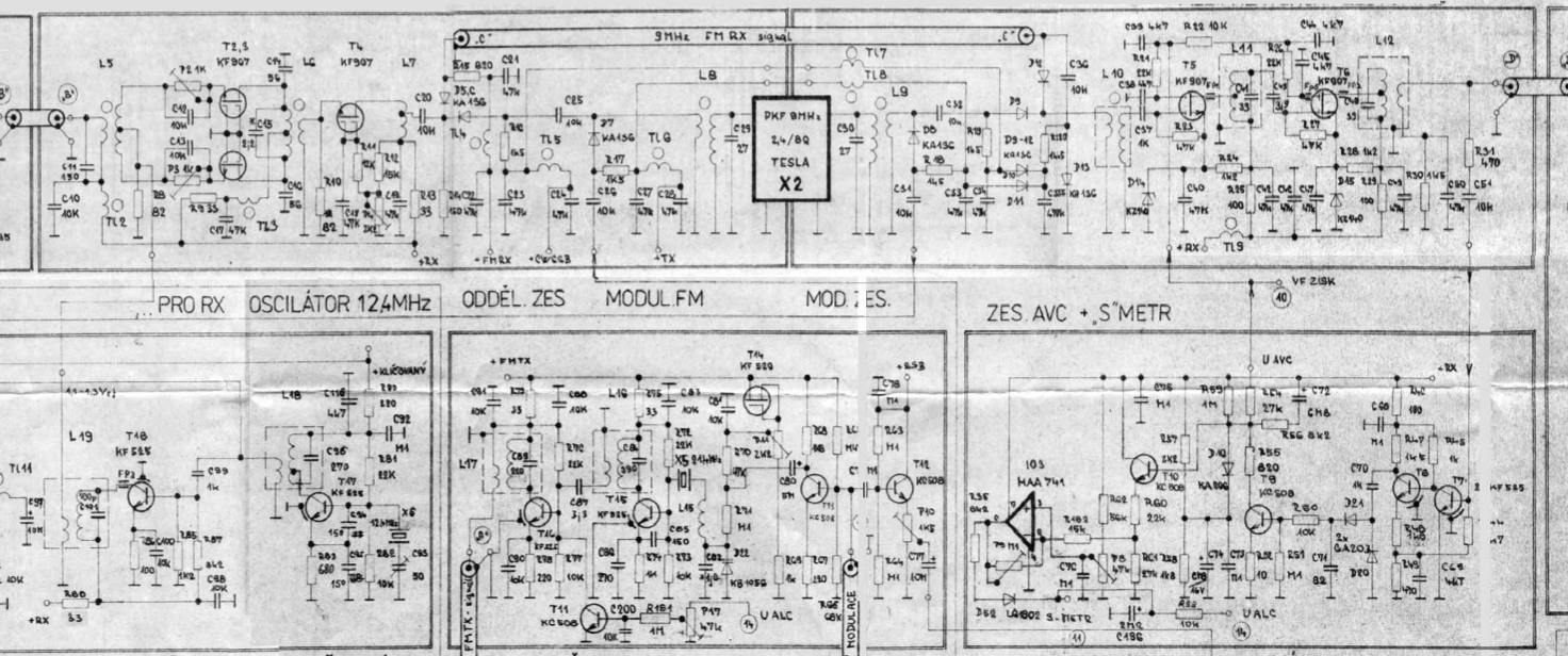
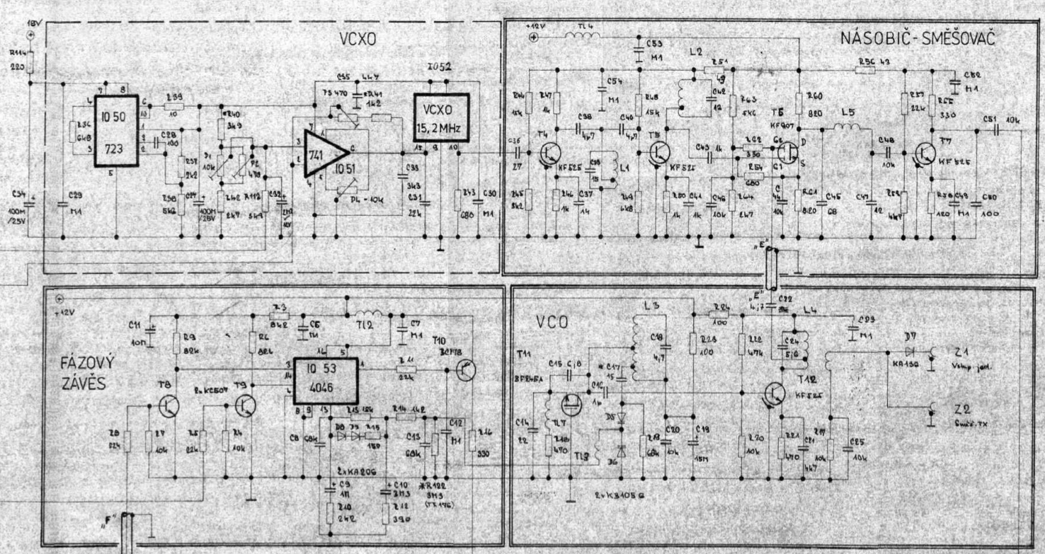
I tuned the symmetry of the mixer and started studying the circuits of the main VCO 122.6MHz. Measuring the frequency of the VCO finally revealed that the frequency really deviates at the moment of the fault. Furthermore, it was confirmed to me that during the fault, the changed frequency remained the same, even if I turned the tuning element, although the frequency change was reflected on the display. Only after exceeding the mentioned 10kHz did the VCO output change. The VCO did not respond to a change of less than 10kHz. This behavior, together with the study of the way the synthesis is connected, led me towards the circuits of the auxiliary VCXO 15.2MHz, which is detuned precisely on the basis of changes in the order of kHz units and below.
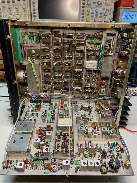
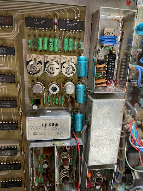
I focused my search on the part of the board containing these circuits. After a rough check of the 10kHz reference, I moved on to the VXCO. The oscillator itself is controlled by the output of IO51 (MAA741), which forms a control voltage based on the voltage reference of IO50 (MAA723) and a "gain change" implemented by two D/A converters - quite a nice idea in my opinion. By measuring, I found that the 15.2MHz signal really trips during a fault and is the cause of the tripping of the entire VCO. The question remained as to why this was happening.
My next suspicion logically fell on the voltage reference with IO50 (MAA723). I measured 9.4V at the output, but I was surprised that even a small load of the 1MΩ reference output by the oscilloscope input will cause a noticeable drop in the reference voltage. I also verified that when a fault occurs, the reference voltage will also change along with the control voltage change. I started cheering that the problem was here - but it turned out to be premature.
After replacing the IO50, I measured a "hard" 10V at its output - certainly this IO slowly left and had an effect on the occurrence of the failure - however, the failure persisted. After a light interlude with examining the condition and measuring the trimmers setting the entire circuit (especially P4 - I don't trust this type, its legs rot and it is poorly adjusted), I again had to state that the core of the poodle does not lie here. By changing the reference, I achieved only a smaller number of occurrences of the malfunction, which made the further search even more difficult. Fortunately, I was already in sight of the target, even if I didn't know it yet.
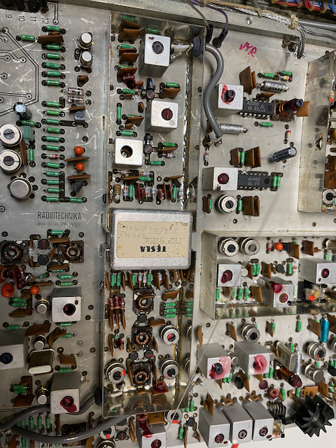
The search moved to the top side of the board, to the D/A converters. These are actually two digital switches on MHB4066 circuits that, based on the BCD state of the input, switch a parallel set of resistors to ground, thus setting the divider on the input of the previously mentioned IO51. One converter solves changes for a step of 1kHz, the other then changes for a step of 100Hz. Here I discovered what I already assumed (or rather what I hoped for), that the outputs of these circuits switch randomly at indeterminate moments for indeterminately long periods of time. By doing so, they actually affect the control voltage for the VCXO, which is randomly retuned as a result. I found out why that was soon, by measuring the inputs of these two IOs (IO34 and IO35). The voltage at the inputs fluctuated around 3.7V, which is apparently a critical decision-making level for the switches themselves. The inputs of these converters are controlled from two multiplexers IO25 and IO26 (MH74157). It is interesting that the supply voltage on the rails of the entire board and the MUXs themselves is a stable 5V, after switching on the cold trx, the outputs of these MUXes are 4.7V, which gradually decreases (within about a minute) to the specified limit level, where it then holds. This level is apparently still sufficient for parallel connected BCD/7segment converters that show values on the display, but it is not enough for the switches themselves.
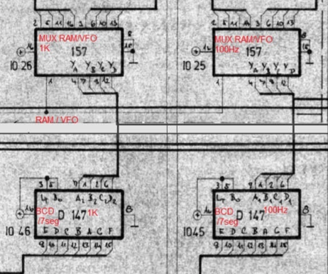
New IOs of this type apparently have sufficiently "hard" outputs, they lose this property as they get older and are not able to excite the output bus with sufficient voltage (I have faced a similar problem of missed parameters before when repairing tuning knob decoders). It is also possible that the inputs of the connected IO load the bus itself more than "when it was young" and pull the voltage to ground. Anyway, I decided to back the MUX outputs with pull-up resistors, which I think is good practice (and I have no idea why this isn't out of the box). I tentatively chose a value of 4d7 and this adjustment seems to have solved the whole problem. It does not appear that any of the concerned IOs protested. It may be that one of the IOs on the incriminating bus is partially defective and my solution will bring it to an earlier end, but it doesn't really matter if I replace those IOs now or when (if) they go away. Now they are known...
It is quite possible that the VCO instability in this type of transceiver that users complain about may have the same cause. Indeed, if the above condition were to occur only on the bus for 100Hz steps, then the total drift of the VCO would be in the range of 100Hz - 1kHz, which can be unjustifiably attributed to other causes - e.g. temperature drift. Therefore, thanks to current experience, when looking for the cause of a drifting VCO in this type of trx, I would recommend checking the voltage state of the said bus.
The entire described anabasis took about three weeks of my free time. Again, I moved a little further in my knowledge and experience - that's why I do it. I decided to write this article in case someone is dealing with the same problem and doesn't have that much energy and space. I will also be happy if any more experienced colleagues - readers - give me feedback or correct me for any mistakes I made during this fix.
I would like to thank my colleagues OK2KKW, OK1HGA and OM6BB, who share schematics, descriptions and other information about the transceiver on their websites, without which I would have a hard time getting through.
Less ▲

 Česky
Česky